Modbus Read/Write Command Line Demo
For this demo we will connect up the the the MyPi board to a second PC running Windows and a PLC simulator, we'll then show how to read/write RTU registers.
At this point you should have the ISO-485 card installed and successfully installed the mbpoll program.
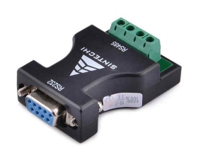
The extra piece of hardware we will need to complete this demonstration will be a RS232-RS485 converter for the Windows PC in order to simulate Modbus RTU comms :
These two items should be wired up as follows :
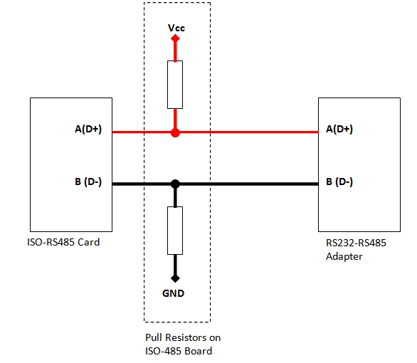
It's worth noting that the biggest problem with field equipment using RS485 is the lack of consistency in the wiring names for D+/D- or A/B as a result it's not unusual for these two lines to often need swapping when connecting up "real" equipment, here using the mbpoll program can be very useful in debugging the setup.
Next we need to install the PLC simulator, to do this download the program from the below website :
https://sourceforge.net/projects/modrssim2
This is a self contained single EXE file, so does not contain an installer - take note of the requirement for a Visual C++ component if you have problems running the software.
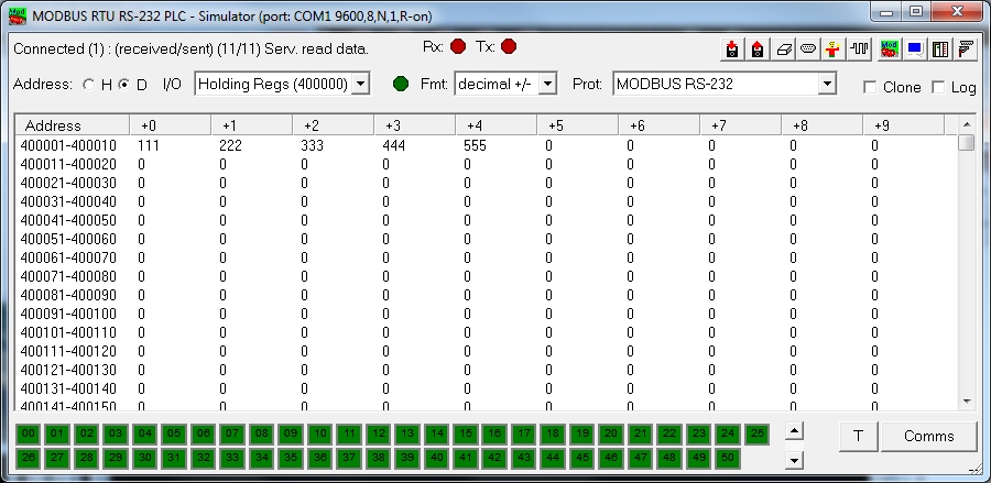
Once loaded you'll be presented with a screen like the below, take note of the three highlighted areas:
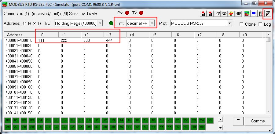
Press F1 at any time for information on how the program works
- The FMT dialog box controls how the registers are shown/configured, we'll keep this at decimal +/- for the moment.
- The cable & port icon controls whether the program is "plugged in" to the selected COM port
- The register window is where most of the action takes place here, in this area click on each of the first row and fill in to match the above.
next on the command line run the following :
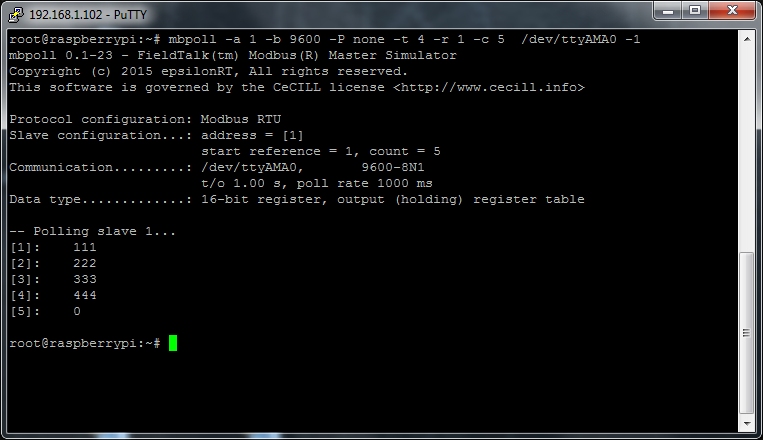
# mbpoll -a 1 -b 9600 -P none -t 4 -r 1 -c 5 /dev/ttyAMA0 -1
Broken down, this will read from the device at address 1 (-a 1) using baud rate 9600 8N1 (-b 9600 -P none) the program will request 5 registers (-c 5) starting at register 1 (-r 1) using function code 4 to read the holding registers (-t 4). The -1 on the end means 'just make 1 poll and stop'
The Raspberry Pi did have a weird quirk with it's serial port, which on the first time it's opened a spurious character is send out, this has been since fixed (as of kernel 4.9) but may result in a CRC error the first time the program is run.
This is the output from a successful read :
Now we'll use the same program to write a register, the below will write 1 register value (555) starting at register 5 (-r 5) in address range 4 (-t 4)
mbpoll -a 1 -b 9600 -P none -t 4 -r 5 /dev/ttyAMA0 -1 555
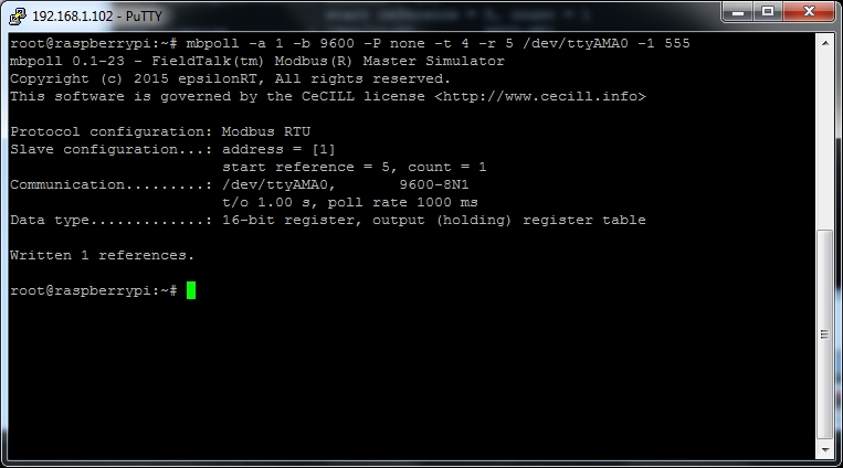
And checking the main windows program we can see the writes have been done correctly
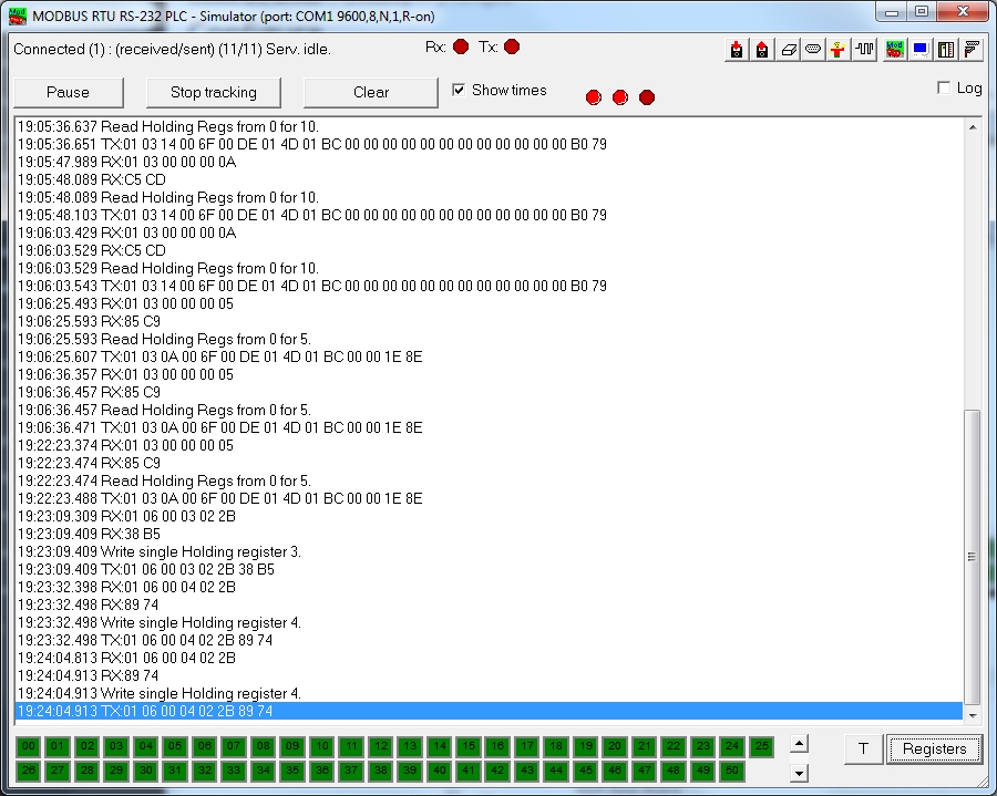
By clicking on the Comms button you can also see the request/response frames :
This is a useful website to help with understanding the Modbus protocol :
The mbpoll program uses an open source C library called libmodbus, which has a very open licence making it ideal for inclusion in any end application and short cutting development time.