ISO-SENSOR-KIT IO Card Setup
Card Description
The Sensor-Kit IO card provides multiple interfaces for common sensors, 8 x 4-20mA Analogue sensors, RS485 Interface, 1-Wire interface.
OS Configuration
To configure the ADC & 1-Wire interfaces run the script below to configure the OS for direct access
root@raspberrypi:~# ./sensorkit-config xt
[info] Configuring ISO-SENSORKIT Card
[info] Creating ADC /dev shortcuts
This can be made permanent and executed during the init startup sequence via the below command sequence :
# chmod +x ./mypi-sensorkit-config.sh
# mv ./mypi-sensorkit-config.sh /etc/init.d
# systemctl enable mypi-sensorkit-config.sh
# reboot
root@raspberrypi:~# i2cdetect -y 1

     0  1  2  3  4  5  6  7  8  9  a  b  c  d  e  f
00:          -- -- -- -- -- -- -- -- -- -- -- -- --
10: -- -- -- -- -- -- -- -- 18 -- -- -- -- -- -- --
20: -- -- -- -- -- -- -- -- -- -- -- -- -- -- -- --
30: -- -- -- -- -- -- -- -- -- -- -- -- -- -- -- --
40: -- -- -- -- -- -- -- -- -- -- -- -- -- -- -- --
50: -- -- -- -- -- -- -- -- -- -- -- -- -- -- -- --
60: -- -- -- -- -- -- -- -- UU -- 6a -- -- -- 6e --
70: -- -- -- -- -- -- -- --
18 = 1Wire Bridge Device
68 = System RTC
6a = ADC 1 (Left hand side ADC)
6e = ADC 2 (Right hand side ADC)
1-Wire
Either read the value directly (in this instance using a temperature sensor :
root@raspberrypi:~# cat /sys/bus/w1/devices/28-0416930e8aff/w1_slave
58 01 4b 46 1f ff 1f 10 eb : crc=eb YES
58 01 4b 46 1f ff 1f 10 eb t=21500
Or we can install a python program to help:
root@raspberrypi:~# apt-get update && apt-get install python3-w1thermsensor python3-setuptools

root@raspberrypi:~# w1thermsensor

	Usage: w1thermsensor [OPTIONS] COMMAND [ARGS]...

	  Get the temperature from your connected w1 therm sensors

	  Available sensors types are:

	    - DS18S20
	    - DS1822
	    - DS18B20
	    - DS28EA00
	    - DS1825/MAX31850K

	Options:

	  --help  Show this message and exit.

	Commands:

	  all        Get temperatures of all available sensors
	  get        Get temperature of a specific sensor
	  ls         List all available sensors
	  precision  Change the precision for the sensor and...

root@raspberrypi:~# w1thermsensor all

 Got temperatures of 1 sensors:

  Sensor 1 (0416930e8aff) measured temperature: 21.5 celsius
A lower precision rating gives a faster reading, so let’s set the devices to 9bit accuracy
root@raspberrypi:~# w1thermsensor precision 9 1
root@raspberrypi:~# w1thermsensor all

 Got temperatures of 1 sensors:

  Sensor 1 (0416930e8aff) measured temperature: 21.5 celsius
4-20mA Analogue Inputs
Once the setup script has run the ADCs can be read directly
/dev/i2cadc1
/dev/i2cadc1/in_voltage0_raw
/dev/i2cadc1/in_voltage0_scale
/dev/i2cadc1/in_voltage1_raw
/dev/i2cadc1/in_voltage1_scale
/dev/i2cadc1/in_voltage2_raw
/dev/i2cadc1/in_voltage2_scale
/dev/i2cadc1/in_voltage3_raw
/dev/i2cadc1/in_voltage3_scale

/dev/i2cadc2
/dev/i2cadc2/in_voltage0_raw
/dev/i2cadc2/in_voltage0_scale
/dev/i2cadc2/in_voltage1_raw
/dev/i2cadc2/in_voltage1_scale
/dev/i2cadc2/in_voltage2_raw
/dev/i2cadc2/in_voltage2_scale
/dev/i2cadc2/in_voltage3_raw
/dev/i2cadc2/in_voltage3_scale
The ADC Interface uses precision 0.1% 100R shunt resistor to convert 0-20mA to 0-2V signal suiable for reading by the ADC.
Current loop sensors can be attached in either "High Side" or "Low Side" configuration. For our card we use Low Side configuration as shown this proved to be the best accuracy and has less scope for problems.
Note that The sensor requires an external power supply (usually +24V) to drive the 4-20mA current loop - the card only measures the current, it does not power the sensor.
Low Side 4-20mA configuration
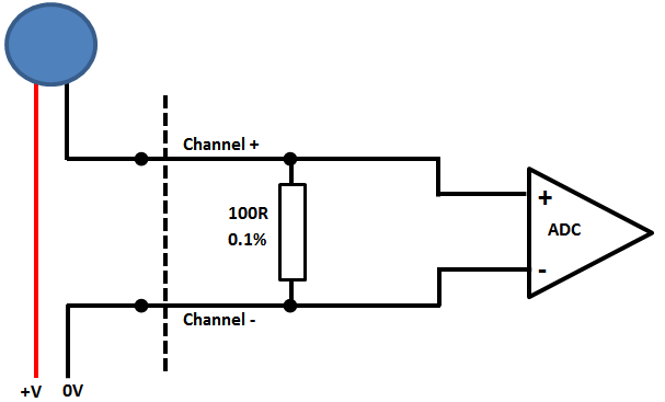
Using a current loop calibrator setup in positon of the blue sensor in the above diagram we cycle through the settings and get results
$ cat /dev/i2cadc1/in_voltage0_raw
399

$ cat /dev/i2cadc1/in_voltage0_raw
799

$ cat /dev/i2cadc1/in_voltage0_raw
1199

$ cat /dev/i2cadc1/in_voltage0_raw
1599

$ cat /dev/i2cadc1/in_voltage0_raw
1997
Dividing these values by 100 gives the results for 4/8/16 & 20mA inputs with approx ±20µA accuracy to source, the shunt resistor has a ±25ppm/°C temperature coefficient so will give stable values over a wide temperature range.
Note that you do not need to be root user to read these values, but only the root user can alter the sample or scaling factors
RS485
The board uses a MAX13487 RS485 line driver, this has transparent automatic hardware flow control and so does not require any additional code to supervise flow control. The RS485 Channel is connected to the UART connected on Pins 21/22 of the IO card
UART to Serial Port Mapping
| Board | Hardware UART | Linux Serial Port |
|---|---|---|
| NT/XT | UART0 / UART1 | ttyS0 / ttyAMA0 |
| SE | UART4 | ttyAMA3 |
The following lines need to be added to /boot/config.txt to enable the hardware UART to appear on the correct pins for the adapter card, these are dependant on carrier board type used used.
Note that depending on the OS version uses these may appear as different tty ports as those stated below
# Integrator Board XT
enable_uart=1  	                                    # Enables UART1 (ttyS0) on GPIO14/15
dtoverlay=disable-bt                                # Moves UART0 (ttyAMA0) to being on GPIO14/15

# Integrator Board NT
dtoverlay=uart0,txd0_pin=32,rxd0_pin=33,pin_func=7  # Enables UART0 onto GPIO32/33

# Integrator board SE
dtoverlay=uart4                                     # Enables UART4 (ttyAMA2)
Our RS485 Modbus app note will be a useful read at this point.
Board Pin out
Numbering left to right :
Left Connector (10way 3.5mm) - Left ADC (0x6A)
| Pin | Function |
|---|---|
| 1 | NC |
| 2 | NC |
| 3 | CH3+ (IN) |
| 4 | CH3- (OUT) |
| 5 | CH4+ (IN) |
| 6 | CH4- (OUT) |
| 7 | CH1+ (IN) |
| 8 | CH1- (OUT) |
| 9 | CH2+ (IN) |
| 10 | CH2- (OUT) |
Right Connector (8way 3.81mm) - Right ADC (0x6E)
| Pin | Function |
|---|---|
| 1 | CH3+ (IN) |
| 2 | CH3- (OUT) |
| 3 | CH4+ (IN) |
| 4 | CH4- (OUT) |
| 5 | CH1+ (IN) |
| 6 | CH1- (OUT) |
| 7 | CH2+ (IN) |
| 8 | CH2- (OUT) |
Main Board (8Way 3.5mm) - Digital Bus
| Pin | Function |
|---|---|
| 1 | +5V 1-Wire Power (150mA Max) |
| 2 | 0V 1-Wire |
| 3 | 1-Wire Data |
| 4 | Not Connected |
| 5 | RS485 A |
| 6 | RS485 B |
| 7 | 0V |
| 8 | Not Connected |