ISO-ADC IO Card Setup
Card Description
The ISO-ADC card features an isolated 16bit ADC capable of reading 0-10V or 4-20mA using precision 0.1% resistors to scale the inputs to the ADC. The 4-20mA inputs are also protected from input wiring errors.
The ADC in use is the common MCP3424 device for which many example C and Python code samples exist, see link below to an example Git repository with demos and libraries for C and Python.
Card 8 Way Connector Pin Out
Left to right this is the pinout of the card
| Pin | Function |
|---|---|
| 1 | Channel 4 Out / 0V |
| 2 | Channel 4 In / +V |
| 3 | Channel 3 Out / 0V |
| 4 | Channel 3 In / +V |
| 5 | Channel 2 Out / 0V |
| 6 | Channel 2 In / +V |
| 7 | Channel 1 Out / 0V |
| 8 | Channel 1 In / +V |
OS Configuration
If you are running the kernel version below or later you can also make use of the precompiled kernel module giving command line access to the ADC
To load and configure the kernel module run the following commands as root user, this installs the driver and then tells the system the MCP3424 ADC device is present on the I2C bus at address 0x6E
# modprobe mcp3422
# echo "mcp3424 0x6e" >/sys/bus/i2c/devices/i2c-1/new_device
This command sets up a shortcut in /dev
# ln -s /sys/bus/i2c/devices/1-006e/iio:device0/ /dev/i2cadc
This should now appear when the below is run
# ls -l /dev/i2cadc/
total 0
-r--r--r-- 1 root root 4096 Mar 10 12:01 dev
-rw-r--r-- 1 root root 4096 Mar 10 12:01 in_voltage0_raw
-rw-r--r-- 1 root root 4096 Mar 10 12:01 in_voltage0_scale
-rw-r--r-- 1 root root 4096 Mar 10 12:01 in_voltage1_raw
-rw-r--r-- 1 root root 4096 Mar 10 12:01 in_voltage1_scale
-rw-r--r-- 1 root root 4096 Mar 10 12:01 in_voltage2_raw
-rw-r--r-- 1 root root 4096 Mar 10 12:01 in_voltage2_scale
-rw-r--r-- 1 root root 4096 Mar 10 12:01 in_voltage3_raw
-rw-r--r-- 1 root root 4096 Mar 10 12:01 in_voltage3_scale
-rw-r--r-- 1 root root 4096 Mar 10 12:01 in_voltage_sampling_frequency
-r--r--r-- 1 root root 4096 Mar 10 12:01 in_voltage_scale_available
-r--r--r-- 1 root root 4096 Mar 10 12:01 name
-r--r--r-- 1 root root 4096 Mar 10 12:01 sampling_frequency_available
lrwxrwxrwx 1 root root    0 Mar 10 12:00 subsystem -> ../../../../../../../bus/iio
-rw-r--r-- 1 root root 4096 Mar 10 12:00 uevent
4-20mA Input Mode
Fit the links in 4-20mA mode as shown below
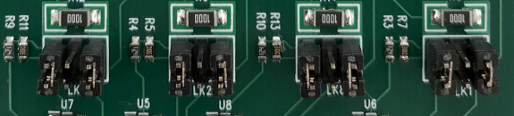
the ADC card uses precision 0.1% 100R resistor to convert 0-20mA to 0-2V
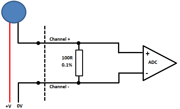
Current loop sensors can be attached in either "High Side" or "Low Side" configuration, in our example we use "Low Side" configuration as this provided the best accuracy and has less scope for problems.
Low Side 4-20mA configuration
With our loop calibrator setup and configured we can cycle through the settings and get results
$ cat /dev/i2cadc/in_voltage0_raw
399
$ cat /dev/i2cadc/in_voltage0_raw
799
$ cat /dev/i2cadc/in_voltage0_raw
1199
$ cat /dev/i2cadc/in_voltage0_raw
1599
$ cat /dev/i2cadc/in_voltage0_raw
1997
Dividing these values by 100 gives the results for 4/8/16 & 20mA inputs with approx ±20µA accuracy to source.
0-10V Input Mode
Fit the links inmode as shown below
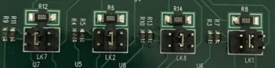
the ADC card uses a precision 0.1% voltage divider to scale down the voltage 5:1 allowing the internal ADC range of 0-2V to read 0-10V
As an example a voltage supply has been attached to ADC Channel 0 to then read the ADC channel run the following commands when set to approx 5V and 10V:
$ cat /dev/i2cadc/in_voltage0_raw
999
$ cat /dev/i2cadc/in_voltage0_raw
1999
$ cat /dev/i2cadc/in_voltage0_scale
0.001000000
The source voltage can then be calcualted as (999* 0.001) * 5 = 4.995V and (1999* 0.001) * 5 = 9.995V
Changing the sample frequency affects the accuracy of the ADC reading taken, as taking fewer samples leads to a higher resolution conversion, which is especially important when working with low voltage or slowly varying signals. Changing the sample frequency will also alter the available scaling factors.
The first step is checking the available sample frequencies and then echo the chosen one into the input sample frequency controller
# cat /dev/i2cadc/sampling_frequency_available
240 60 15 3
# cat /dev/i2cadc/in_voltage_sampling_frequency
240
# echo 15 >/dev/i2cadc/in_voltage_sampling_frequency
# cat /dev/i2cadc/in_voltage_sampling_frequency
15
# cat /dev/i2cadc/in_voltage0_raw
15999
# cat /dev/i2cadc/in_voltage0_scale
0.000062500
# cat /dev/i2cadc/in_voltage_scale_available
0.000062500 0.000031250 0.000015625 0.000007812
So here the lower sample rate has given way to a more accurate reading, and using the same input voltage as before :
(15999x 0.000062500) * 5 = 4.9996875V
Note that you do not need to be root user to read these values, but only the root user can alter the sample or scaling factors