ISO-COMBO I/O Card Setup
Card Description
The COMBO I/O Card is comprised of three types of I/O all of which are isolated from the main card and so usable in an industrial environment.
4 x Opto-isolated digital inputs, wired as individual pairs, these can be driven from 5V to 33V. These have transient over voltage protection devices integrated.
4 x Digital outputs in the form of N/O Relay contacts rated for 24VDC/1A intended for use as either simulating push switch contact closure or low side relay drive.
4 x ADC inputs for the reading 4-20mA sensors via the on-board 100R 0.1% current shunts. These inputs are protected from over voltage, over current or reverse wiring.
OS Configuration
To load and configure the kernel module run the following commands as root user, this installs the driver and then tells the system the MCP3424 ADC device is present on the I2C bus at address 0x6E
# modprobe mcp3422
# echo "mcp3424 0x6e" >/sys/bus/i2c/devices/i2c-1/new_device
We have created a setup file called ioboard.sh which configures the ADC kernel module, GPIO exports for input/output as well as and setting up several /dev shortcuts for all the I/O channels in one go. You can download this from the link at the bottom of this page.
root@raspberrypi:~# chmod +x ./mypi-ioboard.sh
root@raspberrypi:~# ./mypi-ioboard.sh
Usage: ./mypi-ioboard.sh [options]
           og = Original Integrator Board
           nt = Integrator Board NT (CM3+/CM4S)
           xt = Integrator Board XT (CM4)
           se = Integrator Board SE (CM4)

root@raspberrypi:~# ./mypi-ioboard.sh xt
[info] Configuring MyPi IO Card.
[info] Creating MyPi I/O Card /dev shortcuts.
This will create the below shortcuts :
/dev/diginput0
/dev/diginput1
/dev/diginput2
/dev/diginput3

/dev/digout0
/dev/digout1
/dev/digout2
/dev/digout3

/dev/i2cadc/
/dev/i2cadc/in_voltage0_raw
/dev/i2cadc/in_voltage0_scale
/dev/i2cadc/in_voltage1_raw
/dev/i2cadc/in_voltage1_scale
/dev/i2cadc/in_voltage2_raw
/dev/i2cadc/in_voltage2_scale
/dev/i2cadc/in_voltage3_raw
/dev/i2cadc/in_voltage3_scale
/dev/i2cadc/in_voltage_sampling_frequency
/dev/i2cadc/in_voltage_scale_available
4-20mA Analogue Inputs
The ADC Interface uses precision 0.1% 100R shunt resistor to convert 0-20mA to 0-2V signal suiable for reading by the ADC. The inputs are protected by a 33V TVS diode and a TPS26610 4-20mA line protection device.
Current loop sensors can be attached in either "High Side" or "Low Side" configuration. For our card we use Low Side configuration as shown this proved to be the best accuracy and has less scope for problems.
Note that The sensor requires an external power supply (usually +24V) to drive the 4-20mA current loop - the card only measures the current, it does not power the sensor.
Low Side 4-20mA configuration
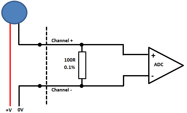
Using a current loop calibrator setup in positon of the blue sensor in the above diagram we cycle through the settings and get results
$ cat /dev/i2cadc/in_voltage0_raw
399

$ cat /dev/i2cadc/in_voltage0_raw
799

$ cat /dev/i2cadc/in_voltage0_raw
1199

$ cat /dev/i2cadc/in_voltage0_raw
1599

$ cat /dev/i2cadc/in_voltage0_raw
1997
Dividing these values by 100 gives the results for 4/8/16 & 20mA inputs with approx ±20µA accuracy to source, the shunt resistor has a ±25ppm/°C temperature coefficient so will give stable values over a wide temperature range.
Note that you do not need to be root user to read these values, but only the root user can alter the sample or scaling factors
Digital/Relay Outputs
The on-board miniature relays are provided to give the user the ability to simulate physical push switch closures or to use as low-side drivers with larger capacity relays as shown below:
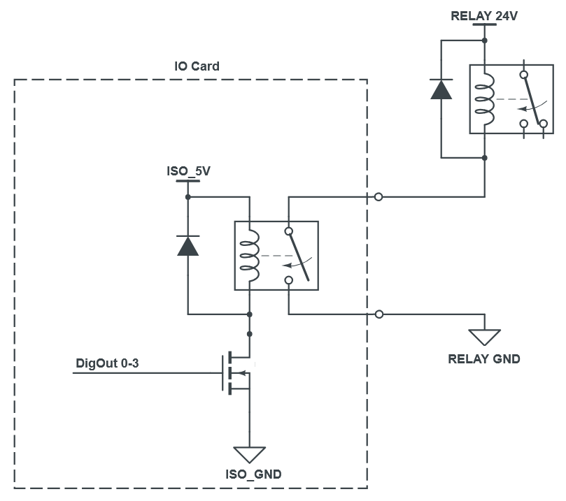
To change a relay state :
$ echo 1 >/dev/digout0

$ echo 0 >/dev/digout0
Digital Inputs
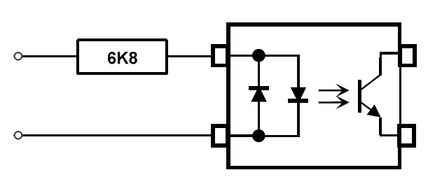
These inputs are connected to the Raspberry Pi GPIO via TLP290-4(GB Optocouplers which are high speed low loss devices and suitable for both DC level reading as well as pwm mode pulse capture. For PWM pulse capture we recommend removing the default Pi GPIO pull up/down on the GPIO line (e.g. via the config.txt file) to ensure most accurate reading.
The optos have a 6K8 input resistor and a 33V Bi-Directional TVS Diode across the input to deal with voltage transients.
To do a basic read use the below command line
$ cat /dev/diginput0
0

$ cat /dev/diginput0
1
For convenience we have added a +5V_ISO and 0V_ISO to pins 9 & 10 of the digital input connector for driving the digital inputs and so can be used with volt-free contacts or for powering a led pulse detector sensor.
Connector Pinouts
Numbered Left to right
Left Connector (10 way 3.5mm) – Digital Inputs
| Pin | Function |
|---|---|
| 1 | DIGIN0-A |
| 2 | DIGIN0-B |
| 3 | DIGIN1-A |
| 4 | DIGIN1-B |
| 5 | DIGIN2-A |
| 6 | DIGIN2-B |
| 7 | DIGIN3-A |
| 8 | DIGIN3-B |
| 9 | ISO-5V-OUT |
| 10 | ISO-GND-OUT |
Right Connector (8 way 3.81mm) - Relay Connections
| Pin | Function |
|---|---|
| 1 | DIGOUT0-A |
| 2 | DIGOUT0-B |
| 3 | DIGOUT1-A |
| 4 | DIGOUT1-B |
| 5 | DIGOUT2-A |
| 6 | DIGOUT2-B |
| 7 | DIGOUT3-A |
| 8 | DIGOUT3-B |
Main Board (8 way 3.5mm) – ADC Inputs
| Pin | Function |
|---|---|
| 1 | CH4+ |
| 2 | CH4- |
| 3 | CH3+ |
| 4 | CH3- |
| 5 | CH2+ |
| 6 | CH2- |
| 7 | CH1+ |
| 8 | CH1- |