Multi RS485 IO Card Configuration
The Multi RS485 board uses multiple SC16IS740 devices to provide I2C and SPI interfaced serial ports
The configuration is done by downloading and installing the device tree overlay files found in the zip file here
Integrator Board NT (CM3/4S) Files
[wget --no-check-certificate 'https://drive.google.com/uc?export=download&id=1pHVvHhVkmF1cfaAXzcOTrPe_S3C9HC1z' -O multiuart.tar.gz]
Integrator Board XT (CM4) Files
[wget --no-check-certificate 'https://drive.google.com/uc?export=download&id=1D9UvhzlU5BvdiPFqLFOYGGyaQqXyQsV1' -O multiuart.tar.gz]
Install Notes :
Disable the serial console and copy all the .dtbo files in the tar zip file to /boot/overlays
# Remove the serial console section from boot cmdline (console=serial1,115200)
root@raspberrypi:~# cat /boot/cmdline.txt
console=tty1 root=PARTUUID=5e843ba5-02 rootfstype=ext4 fsck.repair=yes rootwait

# Disable the serial console service
root@raspberrypi:~# systemctl disable serial-getty@ttyS0.service

# Install device tree files
root@raspberrypi:~# tar -xzf multiuart-cm4.tar.gz
root@raspberrypi:~# cd install-files
root@raspberrypi:~/install-files#  cp *.dtbo /boot/overlays/
Add the single config section below for the respective Integrator board to enable the serial ports, note that the first section may already be in the config.txt file and just need enabling.
# Integrator Board NT
####################################################################################
# Enables UART0 onto GPIO32/33
dtoverlay=uart0,txd0_pin=32,rxd0_pin=33,pin_func=7
# Enables UART1 onto GPIO14/15
dtoverlay=uart1,txd1_pin=14,rxd1_pin=15
# Fixes internal clock to fix baud rate issues.
enable_uart=1
# Correct UART assignment so 32/33 has ttyAMA0 & 14/15 has ttyS0
dtoverlay=uart_swap

dtparam=i2c_arm=on,i2c_arm_baudrate=400000
dtoverlay=spi0-2cs,cs0_pin8=,cs1_pin=7
dtoverlay=i2cuarts
dtoverlay=spiuart1
dtoverlay=spiuart2


# Integrator Board XT
####################################################################################
# Enables UART1 (ttyS0) on GPIO14/15
enable_uart=1
# Moves UART0 (ttyAMA0) to being on GPIO14/15 (if required)
dtoverlay=disable-bt
# Enable UART2 (ttyAMA1) on GPIO0/1
dtoverlay=uart2
# Stop HAT card probe on GPIO0+1 during start-up
gpio=0-1=a4

dtparam=i2c_arm=on,i2c_arm_baudrate=400000
dtoverlay=spi0-2cs,cs0_pin8=,cs1_pin=23
dtoverlay=i2cuarts
dtoverlay=spiuart1
dtoverlay=spiuart2
Reboot the system.
When next booted you can check the I2C ports have been detected by running the below :
root@raspberrypi:~# i2cdetect -y 1
     0  1  2  3  4  5  6  7  8  9  a  b  c  d  e  f
00:          -- -- -- -- -- -- -- -- -- -- -- -- --
10: -- -- -- -- -- -- -- -- -- -- -- -- -- -- -- --
20: -- -- -- -- -- -- -- -- -- -- -- -- -- -- -- --
30: -- -- -- -- -- -- -- -- -- -- -- -- -- -- -- --
40: -- -- -- -- -- -- -- -- UU UU -- -- UU UU -- --
50: -- -- -- -- -- -- -- -- -- -- -- -- -- -- -- --
60: -- -- -- -- -- -- -- -- UU -- -- -- -- -- -- --
70: -- -- -- -- -- -- -- --
The serial ports should now be running as :
root@raspberrypi:~# ls /dev/ttySC*
/dev/ttySC0  /dev/ttySC1  /dev/ttySC2  /dev/ttySC3  /dev/ttySC4  /dev/ttySC5
Baud rates that can be cleanly obtained on all ttySC* ports (note the divisor number is for information only)
Baud	(Divisor)
50	2304
75	1536
150	768
300	384
600	192
1200	96
1800	64
2400	48
3600	32
4800	24
7200	16
9600	12
14400	8
19200	6
38400	3
57600	2
115200	1
If using ttyS0 then be sure to disable it from being a console port
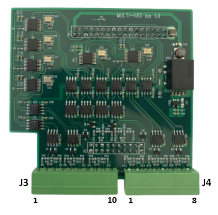
J3
| Pin | Port | Function |
|---|---|---|
| 1 | - | GND |
| 2 | ttySC3 | A |
| 3 | ttySC3 | B |
| 4 | - | GND |
| 5 | ttySC2 | A |
| 6 | ttySC2 | B |
| 7 | - | GND |
| 8 | ttySC1 | A |
| 9 | ttySC1 | B |
| 10 | - | GND |
J4
| Pin | Port | Function |
|---|---|---|
| 1 | ttySC4 | A |
| 2 | ttySC4 | B |
| 3 | - | GND |
| 4 | ttyAMA0 | A |
| 5 | ttyAMA0 | B |
| 6 | - | GND |
| 7 | ttyS0 / ttyAMA1 | A |
| 8 | ttyS0 / ttyAMA1 | B |
Main Board 8 Way
| Pin | Port | Function |
|---|---|---|
| 1 | - | GND |
| 2 | ttySC0 | A |
| 3 | ttySC0 | B |
| 4 | - | GND |
| 5 | - | GND |
| 6 | ttySC5 | A |
| 7 | ttySC5 | B |
| 8 | - | GND |