Power Timer Board Configuration
The MyPi Timer Control board allows the system to :
- - Power system up and down according to a schedule
- - Cut the power to the main board at end of Linux halt sequence (waiting for RTC alarm signal or override input)
This card uses the 8Pin connector to connect the input DC power back into the main board, via the AUX DC-IN 2pin connector J24, via a power FET switch. The logic behind this is as below :
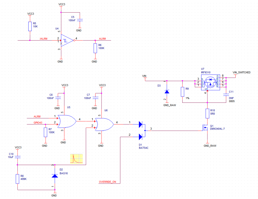
System operation is as follows:
Power applied to the system generates a short one-shot 2-3 Second pulse to U6 pin 2, enabling Q1 to activate the load switch U7.
This pulse provides enough time for the system to boot to the “rainbow” screen, by which time the device tree blob has been loaded.
A custom device tree config (see later) sets GPIO43 high, latching U6 output high, so when the pulse at U6 pin 2 dies away the gate voltage at Q1 stays high for the remainder of the boot sequence and beyond.
A halt or reboot command will at the end of the sequence put all GPIOs into their default state, which in the case of GPIO43 is 0 (low level), causing the system to power off providing none of the other inputs are active (e.g. RTC alarm)
The active low MCP7940N RTC alarm output (/ALRM) is taken through inverter U4 and fed into the OR gate U5, when the RTC alarm is activated U5 pin 1 will latch high until the RTC alarm register is cleared.
A 5-40VDC opto-input provides a 3V DC level to the Wired-OR gate provided by double-diode D1 and “over-rides” the other logic gates, forcing Q1 on.
The 3V logic and RTC are all permanently powered by a low power LDO attached to input voltage, this has a very low current draw of <=1mA at 12V when the system is powered off.
In order to latch GPIO43 high early enough in the boot cycle the device tree blob (/boot/dt-blob.bin) should be re-compiled to have this line added to the pins_cm or pins_cm3 section (depending on whether you are using the CM3 or CM1 device tree source file):
pin@p43 { function = "output"; termination = "pull_down"; startup_state = "active"; polarity = "active_high"; };
Once installed you can check the MCP7940N RTC has been detected at address 6F by the below command :
root@raspberrypi:~# i2cdetect -y 1
     0  1  2  3  4  5  6  7  8  9  a  b  c  d  e  f
00:          -- -- -- -- -- -- -- -- -- -- -- -- --
10: -- -- -- -- -- -- -- -- -- -- -- -- -- -- -- --
20: -- -- -- -- -- -- -- -- -- -- -- -- -- -- -- --
30: -- -- -- -- -- -- -- -- -- -- -- -- -- -- -- --
40: -- -- -- -- -- -- -- -- -- -- -- -- -- -- -- --
50: -- -- -- -- -- -- -- -- -- -- -- -- -- -- -- --
60: -- -- -- -- -- -- -- -- UU -- -- -- -- -- -- 6f
70: -- -- -- -- -- -- -- --
The below script file can be downloaded from the link at the bottom of this page, before running you should install the depandancies, check the souce code for full working description.
root@raspberrypi:~# apt-get install python-smbus python-dateutil

root@raspberrypi:~# ./pwrtimer.py 70
Disabling Alarms
Writing current time to RTC
RTC Time Now Set To  :  06-Aug 14:29:53
Setting Alarm Time
Alarm Time Set To    :  06-Aug 15:39:00
Enabling Alarm